
How to Design the Structure and Appearance of a Street Light Pole?
Sep 22, 2026
The street light pole must hold the luminaire firmly in place under its own weight and wind loads, withstand years of weather and vehicle-induced vibration, and blend into the road landscape. Should its strength, corrosion protection or earthing fail, the result ranges from degraded lighting to a risk to personal safety. Taking the flanged tapered pole - the most widely used type - as an example, this section examines four essentials in turn: the maintenance door, anti-corrosion treatment, strength at the base, and protective earthing; it then sets out the four requirements for appearance design.
Maintenance Door of Solar Street Light Design
The maintenance door is the servicing access opening of a steel light pole. Inside the door there is usually an electrical mounting plate, whose main function is to connect the luminaire and the cable. Fuses and terminal blocks are normally mounted on this plate. The way the door opens is very important, and designs differ from one manufacturer to another. On the one hand, servicing must be convenient; on the other hand, theft must be prevented - hence the use of a specially made door key.
Table 1 lists the maintenance door dimensions corresponding to common pole heights. For the dimensions represented by A, B and C in Table 1, please refer to the figure below. A is the height of the lower edge of the maintenance door above the ground; it should be set for the comfort and convenience of the worker, and should preferably be 500–600 mm. C is the width of the maintenance door; it should allow convenient replacement of the ballast and fuse, and is generally not less than 100 mm. B, the height of the maintenance door, depends on whether the pole carries a single-arc or double-arc luminaire and on the pole diameter at the door location; it is generally 200–1000 mm.
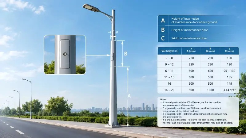
If the maintenance door is made too large - that is, if the values of B and C are too great - the strength of the steel pole will be directly affected; if it is too small, the worker's operation will be hampered. Where the values of B and C are too large, appropriate reinforcement measures should be taken to ensure that the strength of the pole is sufficient for safety. An inner-and-outer double-door arrangement may also be adopted.
|
Pole height (m) |
A (mm) |
B (mm) |
C (mm) |
|
7~8 |
220 |
200 |
100 |
|
9~12 |
220 |
280 |
120 |
|
6~11 |
500 |
600 |
95–130 |
|
11~15 |
600 |
500 |
135 |
|
16 |
600 |
500 |
145 |
|
14~20 |
500 |
1000 |
3.14 d/4 |
Anti-corrosion Treatment of Steel Light Poles
Because of the nature of steel itself, protection against corrosion is a key concern for steel light poles during both storage and service. Corrosion of a steel pole is caused by the chemical or electrochemical action of the surrounding medium. According to the medium involved, it is classified as atmospheric corrosion, seawater corrosion, bacterial corrosion and so on. Atmospheric corrosion is by far the most common, because a steel pole is in contact with the atmosphere during machining, transport, storage and service alike, so the conditions for atmospheric corrosion are present at all times.
1.Factors causing corrosion of steel poles.
The main factors that cause a steel pole to rust and corrode are as follows:
1.1Relative humidity of the atmosphere.
At a given temperature, the ratio of the water vapour content of the air to its saturation water vapour content is called the relative humidity. Below a certain relative humidity the rate of rusting and corrosion of a steel pole is very low, whereas above that relative humidity the rusting rate rises sharply; this value of relative humidity is called the critical humidity. The critical humidity of steel is about 75%. Atmospheric relative humidity has the greatest influence on the corrosion of metals: once the atmospheric humidity exceeds the critical humidity, a film of water or water droplets forms on the steel surface, and if harmful impurities in the air dissolve in that film or those droplets, an electrolyte is formed and corrosion is accelerated.
1.2 Air temperature and humidity.
Atmospheric temperature and humidity affect rusting together. The rate of rusting depends on the water vapour content of the air and increases as the air temperature rises. This is especially true in humid environments, where the higher the temperature, the faster the rusting - and all the more so above the critical humidity. In addition, if there is a temperature difference between the atmosphere and the steel, condensation forms on the cooler surface of the pole and also causes rusting.
1.3 Corrosive gases.
Among the corrosive gases in polluted air, sulphur dioxide has the greatest effect on the rusting of steel poles. Oxygen in the atmosphere acts on the rusting of steel poles most persistently, exerting its effect at all times.
1.4 Other factors.
The atmosphere contains large quantities of dust - smoke, coal ash, chlorides, acids, alkalis, salts, etc. - among which chlorides have the greatest effect.
2. Anti-corrosion treatment.
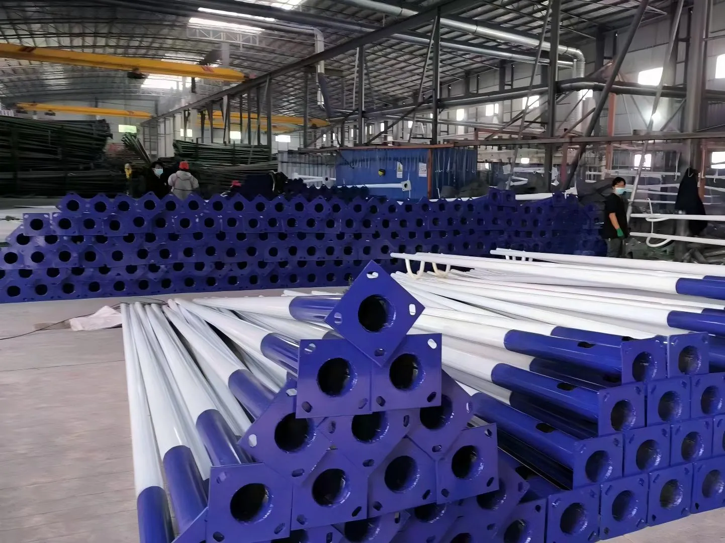
To prevent rust and corrosion from reducing the structural strength of a pole and creating a safety hazard, anti-corrosion treatment must be applied to steel poles. Anti-corrosion methods are preventive measures aimed at the causes of corrosion. Rust prevention means avoiding or slowing the effects of moisture, high temperature, oxidation, chlorides and other factors. The methods commonly used at present are as follows:
2.1 Hot-dip galvanizing.
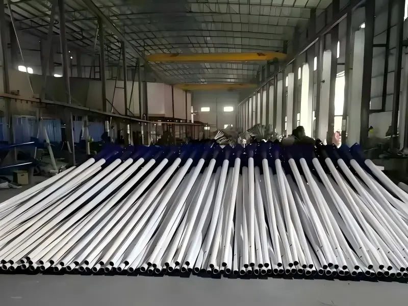
The process and method of immersing pre-treated steel or cast-iron parts in molten zinc so that a coating of zinc and/or zinc–iron alloy is formed on their surface. The zinc coating thickness should reach 65–90 μm. The zinc coating of galvanized parts should be uniform and smooth, free from burrs, drips and excess lumps; the coating should be firmly bonded to the steel pole substrate, and after a hammer test the coating should not peel off or blister.
2.2 Powder coating.
Powder coating is applied after hot-dip galvanizing. The powder should be an outdoor-grade powder; the coating must be free from peeling and cracking, and no peeling or cracking may occur when the bond strength between coating and substrate is tested. Powder coating further improves the corrosion resistance of the steel pole and greatly enhances its decorative appearance, with a wide choice of colours; its drawback is the relatively high cost.
Strength Calculation at the Base of a Steel Light Pole
A light pole is subject to two forms of loading.
One is its own self-weight. For a single-arc pole, the self-weight arises from the weight of the lamp arm and luminaire head, which produces a bending moment in the plane of the lamp arm. For a double-arc pole, the situation varies with the lengths of the two arms: after the bending moments produced by the weights of the arms and luminaire heads of the long and short arcs partially balance each other, the difference between them, acting in the plane of the arms, constitutes the self-weight moment.
For a double-arc pole with arcs of equal length, the moments balance if the luminaires and their associated electrical components in that plane are identical; if they are not identical, a bending moment is produced in the plane of the arms by the difference in the weight of the luminaires and their electrical components.
Besides self-weight, the other load on the pole comes from wind. The strength of the pole must satisfy the following:
- When the wind direction is parallel to the plane of the lamp arm, the maximum bending moments produced by the wind-exposed areas of the luminaire head and the pole at the cross-sections at the bracket-to-pole connection, at the maintenance door and at ground level must be less than the allowable value;
- When the wind direction is perpendicular to the plane of the lamp arm, then in addition to the bending moment produced by the wind-exposed area of the shaft itself, the wind load on the luminaire head and lamp arm of a single-arc pole also produces a bending moment and a torque in the plane of the pole; all these moments must be less than the allowable value.
The wind load depends on the location, region and altitude of the pole being calculated, that is:
p0=Kv2/16
p0 is affected by the various coefficients substituted into the calculation, such as the dimensions of the pole, the form of the pole cross-section, and the fundamental period of one oscillation waveform.
The uniformly distributed wind pressure on the pole is calculated by:
p1=p0dˉ H
In the above two equations: p 0 is the wind pressure per 1 m² of the pole (Pa); K is the aerodynamic coefficient, which according to the standard is K=0.7 for circular elements (it is recommended that K=1.0 be taken for regular hexagonal and octagonal sections); v is the wind speed, generally v=25 m⋅s−1, H is the height of the pole (m); and dˉ is the average diameter of the pole (m), where
dˉ=(d1+d2)/2
Here d1 is the top diameter of the pole (m) and d2 is the base diameter of the pole (m). The taper of a pole is generally 1/90, 1/100 or 1/110, or is non-uniform.
The wall thickness of steel light poles 12 m high and below is 4 mm. When the wall thickness is 3.0 mm, the pole is liable to vibrate under the action of wind and of passing heavy vehicles, which loosens its bolted connections and affects the luminaire.
Protective Earthing of Steel Light Poles
Steel light poles, control boxes and similar installations contain electrical equipment inside them, and they can be touched by a person standing on the ground at any time. Once the insulation fails and the pole body becomes live, the touch voltage is applied directly to the human body, with serious consequences. Therefore, any metal enclosure that contains electrical equipment and can be touched by a person standing on the ground must be reliably connected to a protective conductor - that is, earthed or connected to neutral.
Low-voltage distribution systems are classified by their earthing arrangement into three types - TN, TT and IT - and the TN system is further divided into three types according to how the neutral conductor (N) and the protective conductor (PE) are combined:
- TN-S system: the N and PE conductors are kept separate over the whole length from the source. The PE conductor does not normally carry operating current, so safety is the best.
- TN-C system: the N and PE conductors are combined into a single PEN conductor, which saves one conductor. However, the PEN conductor normally carries operating current, and if it breaks, the equipment enclosure is raised to the phase voltage through the load circuit, so the safety margin is low.
- TN-C-S system: the front section uses a PEN conductor, which is split into separate N and PE conductors at the incoming end of the control box and must not be recombined thereafter. This combines safety with economy of wiring and is the practice most widely used in road lighting projects.
In the TN-C system, since the N and PE conductors are combined, the following requirement must also be met: for low-voltage electrical equipment with a directly earthed neutral, in order to ensure automatic disconnection of the faulty section, the short-circuit current must be not less than 4 times the rated current of the fuse element at the nearest point, or not less than 1.5 times the instantaneous (or short-time-delay) operating current of the automatic switch.
The actual practice is as follows: φ10 mm hot-dip galvanized round steel is laid along the whole line alongside the buried cable and buried directly in the ground (Figure 6.3.9); the PEN conductor is connected to the transformer earthing network at the transformer and is reliably connected at two points to all control boxes, steel light poles, metal light bases and similar parts along the line; a separate earthing electrode is installed at the head end, the far end and each branch point of the line and at every third pole; the resistance of an individual earthing electrode must not exceed 10 Ω and that of the whole earthing network must not exceed 4 Ω; where these limits are exceeded, a long-acting resistance-reducing agent may be used, but corrosive substances such as common salt are prohibited - they reduce resistance in the short term but corrode the earthing body in the long term.
Earthing is the last line of defence and cannot replace insulation. Inside the maintenance door, cables should be connected by means of a junction box with a plastic enclosure or a pin-type terminal bracket; the insulation level of conductors, ballasts and other components should be raised, manufacturers should be strictly selected and testing strictly carried out, and an "installation workmanship standard" should be implemented. Only by carrying leakage-prevention measures through the whole process of material selection, construction, acceptance and operation and maintenance, and by correctly applying the three-wire or five-wire system, can the safety of steel light poles finally be assured.

Appearance Design of Steel Light Poles
The fundamental function of a light pole is to hold the luminaire in the proper position and provide support. At the same time, the pole also has a decorative role. For road users - pedestrians, cyclists and motor vehicle drivers alike - the form of the pole within their field of view cannot be ignored: people may not notice the luminaire high on top of the pole, because it is much smaller than the pole, yet the pole itself strikes the eye directly in the direction of horizontal travel. Hence, with economic development and rising aesthetic standards, the appearance of light poles is receiving increasing attention.
Appearance design of light poles arises from concern for the road landscape. It should be subordinate to the design of the landscape of the road as a whole, and must at the same time first satisfy lighting requirements and safety considerations. The following aspects must therefore be considered in the appearance design of a light pole.
1. Safety requirements
Safety is the basic requirement that a designer should consider first at all times. The safety of a light pole is assured by several aspects, such as the quality of the pole steel and the anti-corrosion treatment; the aspects related to appearance design are load calculation and ensuring strength. Sometimes a pole with a complex shape is indeed very attractive, but the more complex the structure, the more complex the strength calculation and the greater the difficulty of assuring safety; strict verification is therefore essential in the selection of such poles.
2. Lighting requirements
Lighting requirements are another basic requirement of pole appearance design. As will be clear from the content of Chapter 7, a designer goes through complex work to select suitable luminaires and light sources and to determine the position of each street light - including its height, spacing, bracket length and tilt angle - and all these parameters are governed by the pole.
To ensure lighting quality in a specific road lighting project, once the mounting parameters of the luminaires have been determined, the design of the pole must meet the requirements of those parameters: whatever the appearance of the pole, the height of the luminaire fixing point must not change, the horizontal length of the lamp arm must not change, and the tilt angle of the lamp arm must not change either (except where the luminaire itself permits adjustment of its mounting angle). Otherwise the lighting quality will deviate from the intended design result to a greater or lesser degree.
Another aspect of the lighting requirement is that installation and maintenance should be convenient; from this point of view, the appearance of the pole should not be over-complex.

3. Aesthetic requirements
Aesthetic requirements are the starting point of pole appearance design. The appearance of a pole cannot be judged in isolation but should be assessed comprehensively together with all related factors. On the smaller scale, these factors include the styling of the luminaire, the cross-sectional shape of the road, whether the pavement is asphalt or cement concrete, the roadside planting, the style of roadside sculpture, and the class and nature of the road; on the larger scale, they include the built or natural environment on both sides of the road, the function of the district, the history of the district, and the aesthetic tastes of the people of the city concerned.
The visual appeal of a steel pole's appearance derives mainly from the combination and variation of the lines of its structural parts, and in particular from changes in the shape of the lamp arm and the addition of decorative lines; in more elaborate designs the lamp arm is shaped into various profiles, and even the main pole is styled together with it.
Visual appeal also comes from the surface treatment of the pole. With the development of powder coating technology, more and more poles have been given coats of colour in a wide range of shades, abandoning the monotonous grey of the galvanized pole of the past and adding more elements of beauty.
4. Cost requirements
The introduction of various pole types has indeed enriched the visual scene, but beauty comes at a price. Every different shape increases the difficulty of machining, and some even require the development of special moulds; to ensure strength, complex poles must be reinforced, which increases the amount of steel used; in addition, powder coating is widely applied, and so on. All of this substantially raises the manufacturing cost of the pole.
There is also a hidden cost that is easily overlooked: some highly individual pole designs fail to achieve the intended beautification and instead become a form of visual pollution, affecting the road and even the image of the city - and that cost is far too high.

Conclusion
A street light pole may be only a supporting component, yet it is where safety, function and appearance meet: the maintenance door, corrosion protection, base strength and earthing determine whether it stands safely and durably, while its appearance determines whether it harmonises with the road environment. The two are a matter of priority, not opposition - safety and lighting quality are non-negotiable prerequisites, and aesthetics can only follow.